
| For Ray-Lin Index, click HERE ***** To return to the BCOIE Chapter website click HERE or on our logo above. |
|
Studebaker Hawk Clock Repair
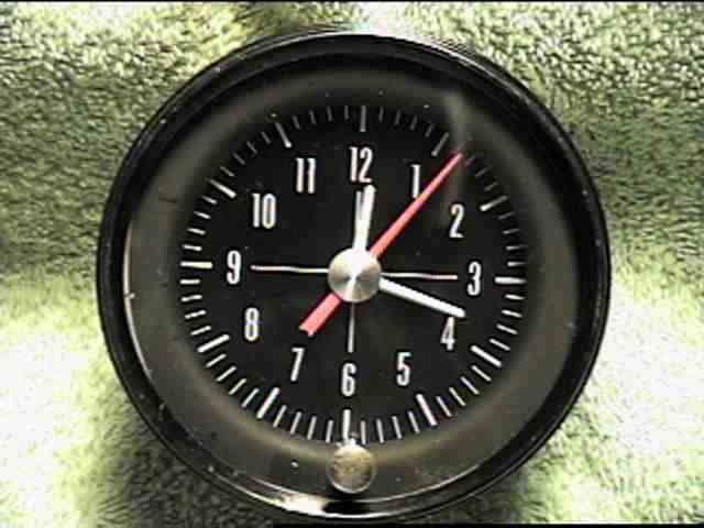
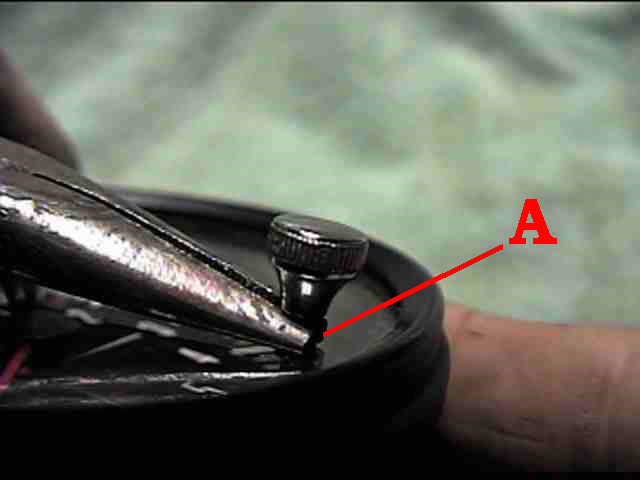
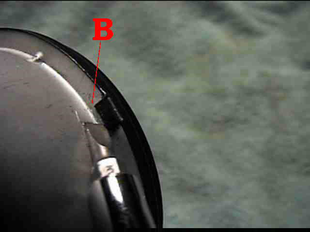
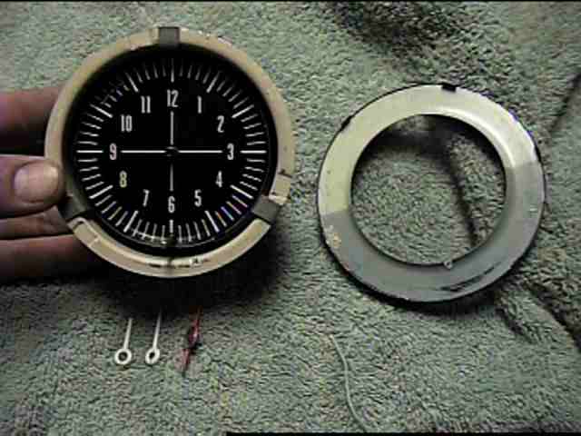
For purposes of this page, I will be using a clock from a 1962 GT Hawk as a demonstration. Most other Studebaker clocks operate in much the same way. I have rebuilt several clocks from '56 to '64 Hawks and '63-'64 Larks. I have yet to do one for an Avanti. The 3 most common ailments I have found are: corrosion on the "points" surfaces, general lack of lubrication, and a small wire broken for the winding pawl. The photos and descriptions that follow should help anyone repair their own clock. If you are going to try this for yourself, be sure to READ ALL THE INSTRUCTIONS FIRST! there are a few things to watch out for during disassembly that cannot be shown or described until later stages. STEP 1: Getting Started To get inside the clock, you must first remove the setting knob. To do this, you must grab the knob and pull it outwards from the clock face. Using pair of small needle nose pliars- grip the shaft (fig A). You should be able to unscrew the knob from the shaft by hand- however, if it is too tight, carefully use another pair of pliars to break it loose. When the knob is removed, you can then carefully pry up the tabs that hold the outer bezel to the clock- using a small screwdriver (fig B). Do not bend them more than 90 degrees, and refrain from bending them back and forth. They are quite brittle and will break if bent too often.
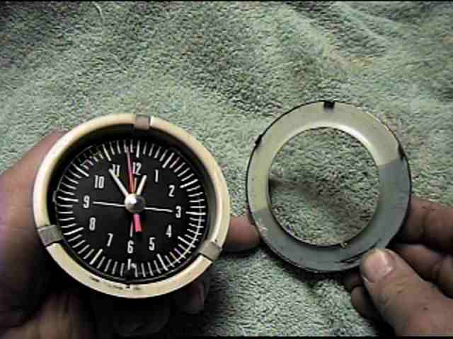
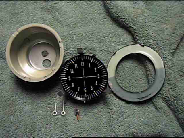
STEP 2: Disassembly The bezel, glass, and retaining ring can now be removed. This will allow access to the clock's hands. The second hand will pull straight off with a little twisting. The minute and hour hands should be removed by hand also, though a small screwdriver may be needed to carefully pry them off. Turn the clock over, and push the rubber seal (around the power wire screw) through the opening. The inside mechanism should just fall out.
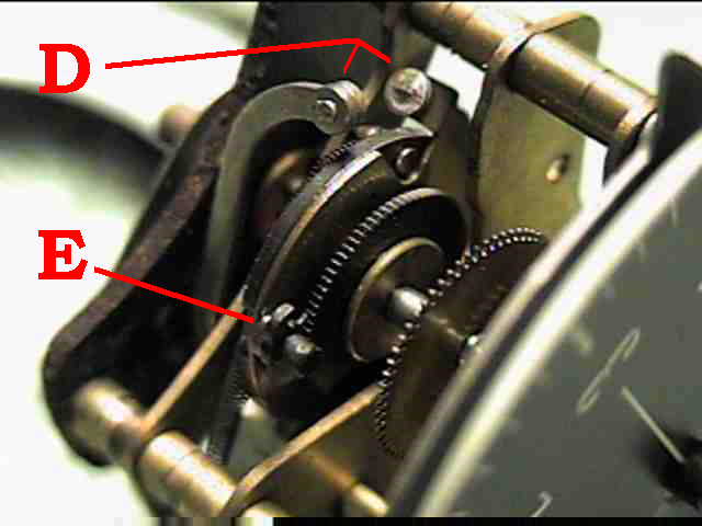
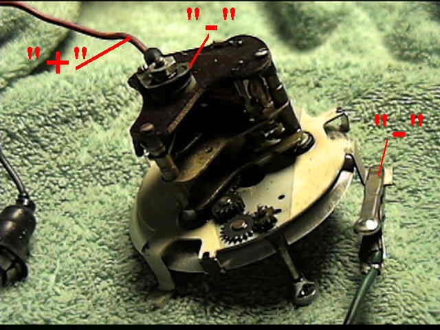
STEP 3: Cleaning the points- Checking the wiring Turn the clock until you see the set of points (fig D). They will probably be closed, so you may need to open them by rolling the wheel that the "fixed" point is attached to. Inspect the points for burning, carbon or other corrosion. Use a point file or 180 grit sandpaper to clean the points up. By releasing the ratchet mechanism (fig E) , you can cause the points to close, and use the sandpaper between them. Close the points to check for proper alignment. if they do not align squarely, you can bend the point arm with the needle-nosed pliers.
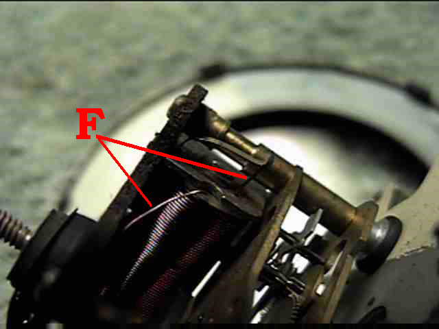
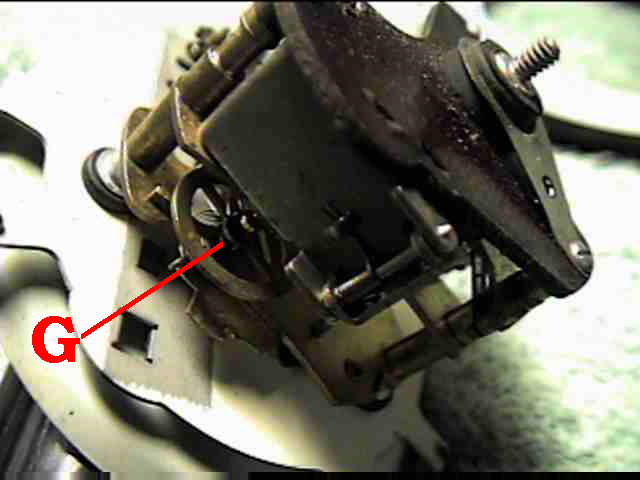
The next thing to check for is the little wires for the Winding Pawl (fig F). The tiny short wire is the most likely to burn and break, but I have seen the heavier wire bad also. If either of these wires are broken, they will need to be re-soldered into place. This Pawl gets current from the battery when the points close. A magnetic field forms, and the resulting magnet "winds" the clock by pulling apart the set of points on the wheel (fig D above)- you will hear an audible "click". The spring then takes over and runs the clock until the points close again. Step 4: Lubrication Once you have determined that the contact points and winding pawl wires are in good shape, You can use an electrical spray cleaner to clean the mechanism. Spray it generously in short bursts and allow 10-15 seconds between blasts. Try to refrain from using Carburetor or Brake cleaners, as they can damage the paint on the dial face, and the insulation on the winding pawl coil. Once clean and dry, You will need to lubricate all the gears and shaft points. I use "Watch Oil" from a jeweler. I take a thin wire and dunk it in the oil- then touch all the gears and pivot points. Do NOT use WD-40 or similar spray lubricants- the propellents usually allow the lubricant to dry out too quickly for our purposes. Once thoroughly lubricated, you must "make" the clock run to work the lubricant into all the necessary places. You can manually "wind" the spring, by rolling the points apart all the way (fig D above) . I then hand-operate the spring wheel- - (fig G above) this is one area you need to be really careful with. Rough handleing may damage the spring, and you can certainly knock it out of it's cradle. It is pretty sensitive, and once out, it is nearly impossible to replace. However- this important part needs to be lubricated and "actuated" by hand to help work the lubrication into the mechanism. I usually will "rock" the unit to get the wheel moving. It should run 1 1/2 to 3 minutes on one winding. I'll set the unit down in the garage, and pick it up and rock it every few minutes when I walk by. Keep an eye on the contact points, and re-spread them whenever they are closed. When the clock will consistently run by itself until the points close, it's time to add power.
I like to use my 10 amp battery charger to test-run the clocks I rebuild and use the original clock wire with a 3-amp inline fuse. Follow this procedure before adding power:
The clock should run on it's own, you may need to "help" restart it on occassion. Most of the original clocks will just stop and need a tap or ground adjustment to continue. This is normal- remember, these things are 35+ years old. Step 5: Assembly
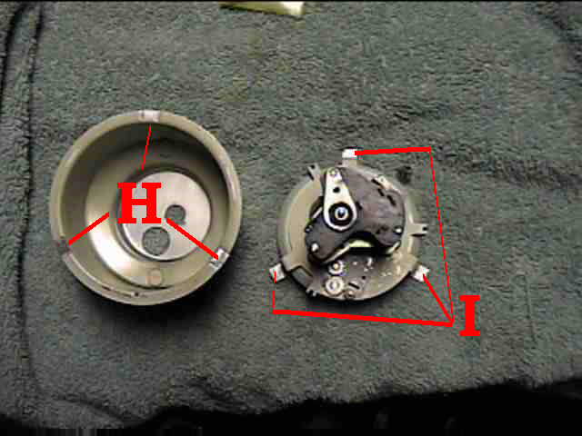
The reassembly is just the reverse of the disassembly- with one modification. Studebaker guages are notorious for bad grounds. I like to take the outer clock shell and remove the paint from the recessed areas of the shell (fig H ), and the tabs on the mechanism (fig I) . Upon assembly, this will provide a better ground for the mechanism, and may help prevent future problems. I also like to add a ground wire from one of the clock mounting screws to the dash's "mounting bar".
|
|
www.StudebakerSoCal.com |